


Unit 2 Summary
| Lesson | Topic | Key content covered |
|---|---|---|
| Lesson 2.1 | Role of microcontrollers in IoT | MCU architecture, MCU vs MPU vs SBC, power consumption, execution cycle, serial communication protocols. |
| Lesson 2.2 | Arduino and ESP32 configuration | Board specifications, pinout reference, IDE setup, digital I/O, PWM, debounce, Wi-Fi connection code. |
| Lesson 2.3 | Analog and digital signals | Signal types, ADC resolution, conversion formula, LDR circuit, ESP32 ADC limitations, DAC, Serial Monitor debugging. |
Quick Reference — Key Functions
| Function | Board | Purpose |
|---|---|---|
| pinMode(pin, mode) | Both | Configure a pin as INPUT, OUTPUT, or INPUT_PULLUP |
| digitalWrite(pin, HIGH/LOW) | Both | Set a digital output pin HIGH or LOW |
| digitalRead(pin) | Both | Read a digital input pin (returns 0 or 1) |
| analogWrite(pin, 0–255) | Uno only | Output PWM on a ~-marked pin |
| analogRead(pin) | Both | Read analog voltage (0–1023 Uno, 0–4095 ESP32) |
| ledcSetup(ch, freq, res) | ESP32 | Configure a PWM channel |
| ledcAttachPin(pin, ch) | ESP32 | Attach a GPIO pin to a PWM channel |
| ledcWrite(ch, duty) | ESP32 | Set PWM duty cycle on a channel |
| dacWrite(pin, 0–255) | ESP32 | True analog output on DAC pins (GPIO 25 or 26) |
| Serial.begin(baud) | Both | Initialise serial communication (9600 or 115200) |
| millis() | Both | Return milliseconds since power-on (non-blocking timing) |
| map(val, f1, f2, t1, t2) | Both | Rescale a value from one range to another |
| WiFi.begin(ssid, pass) | ESP32 | Connect to a Wi-Fi network |
| WiFi.localIP() | ESP32 | Return the device’s IP address after connection |
Key Terms Glossary
ADC
Hardware that converts a continuous analog voltage into a discrete digital number.
Analog signal
A signal that varies continuously within a range of values.
Bootloader
Small program stored in MCU flash that initialises hardware and loads the user program.
DAC
Hardware that converts a digital number into a proportional analog voltage.
Deep sleep
Low-power MCU state where most circuits are off; uses µA of current.
Debounce
Technique to prevent multiple false readings from a single mechanical button press.
Digital signal
A signal with only two valid states: HIGH (logic 1) or LOW (logic 0).
Duty cycle
The percentage of one PWM period during which the signal is HIGH.
EEPROM
Electrically Erasable Programmable Read-Only Memory — non-volatile storage for configuration.
GPIO
General Purpose Input/Output — programmable digital I/O pin on a microcontroller.
I2C
Inter-Integrated Circuit — two-wire serial protocol (SDA + SCL) for connecting sensors.
MCU
Microcontroller Unit — a complete computing system on a single chip.
PWM
Pulse Width Modulation — digital technique to simulate analog output by varying on-time.
SRAM
Static RAM — fast volatile memory used for variables and the program stack.
SPI
Serial Peripheral Interface — fast four-wire serial protocol for sensors and displays.
UART
Universal Asynchronous Receiver-Transmitter — two-wire serial port (TX/RX).
Further Reading & Resources
- Arduino Language Reference — docs.arduino.cc/language-reference
- ESP32 Arduino Core Documentation — docs.espressif.com/projects/arduino-esp32
- ESP32 Pinout Reference — randomnerdtutorials.com/esp32-pinout-reference-gpios
- Tinkercad Circuits (free, browser-based) — tinkercad.com
- Wokwi Simulator — wokwi.com — free browser-based Arduino and ESP32 simulator with Wi-Fi simulation support

You may also like

Nyereka Tech and Tumba College Explore Opportunities for Collaboration
September 25, 2026
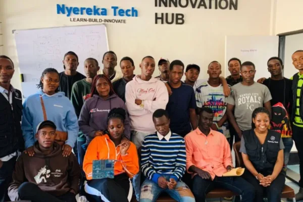
The Launch of our IoT Innovation Hub
May 7, 2026

Partnership with MakerSpace Kigali
May 7, 2026