


Basics of electronics components
Basics of electronics components
- Introduction to Electronic components
Resistors
A resistor opposes the flow of electricity through a circuit. Resistors have a set value.
Since voltage, current and resistance are related through Ohm’s law, resistors are a good way to control voltage and current in your circuit.
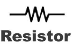
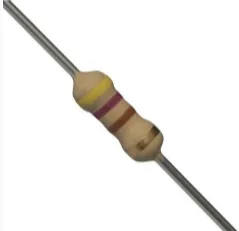
More on RESISTOR
1st band= 1st number
2nd band=2nd number
3rd band= # of zeros/ multiplier
4th band= tolerance

Units
Knowing your units is important!
Kilo and Mega are common in resistors
Milli, micro, nano and pico can be used in other components
- K (kilo) = 1,000
- M (mega) = 1,000,000
- M (milli) = 1/1,000
- u (micro) = 1/1,000,000
- n (nano) = 1/1,000,000,000 (one trillionth)
- p (pico) = 1 / 1,000,000,000,000 (one quadrillionth)
Inductor
When current flows through a wire that has been coiled, it generates a magnetic field. This magnetic field reacts so as to oppose any change in the current. This reaction of the magnetic field, trying to keep the current flowing at a steady rate, is known as Inductance and the force it develops is called an inductor.
The wire coil in the relay is the simplest form of an inductor, which is a passive energy storage element that stores energy in the form of a magnetic field.
It can be shown that, when a current flows in a wire, a magnetic field is produced around the wire. If the wire is formed into a coil, the magnetic field resembles that of a bar magnet.
The magnetic field is represented by lines of force that show the direction of the field in and around the coil.
Inductors are used extensively in analog circuits and signal processing. Inductors in conjunction with capacitors and other components form tuned circuits which can emphasize or filter out specific signal frequencies.
Inductors are not polarized and may be installed in either direction.

Capacitors
A capacitor stores electrical energy.
This pool of electrons is available for electronic components to use. Capacitance is measured in Farads. The small capacitors usually used in electronics are often measured in microfarads and nanofarads.
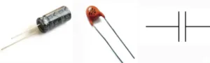
Some capacitors are polarized.
Note the different length terminals on one of the capacitors.
Polarity of capacitors (51x5ds9oGi!^
- The shorter terminal goes on the negative side.
- The stripe is on the negative terminal side of the capacitor.
- The board is marked for positive or negative.
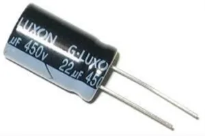

TYPES OF CAPACITOR
- Electrolytic capacitor
- Ceramic capacitor
- Mica capacitor……
Diode
A diode is a one-way valve for electricity. It is a component with an asymmetrical transfer characteristic. A diode has low (ideally zero) resistance in one direction, and high resistance in the other direction.
It is used for the rectification circuits(AC-DC)
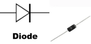
Diodes will protect your electronics
Light emitting diode (LED)
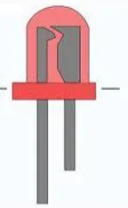
A light emitting diode (LED) is a semiconductor light source. When electricity is passing through the diode, it emits light.
It is mostly used as indicator in electronic circuits.

Variable resistor / Potentiometer
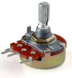
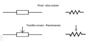
A potentiometer is a variable resistor. As you manually turn a dial, the resistance changes.
Transistors
A transistor is a semiconductor device used to amplify and switch electronic signals and electrical power. The value of transistor is printed on its body.
This is our electronic switch!
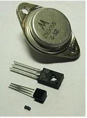

How a transistor works
A voltage or current applied to one pair of the transistor’s terminals changes the current through another pair of terminals.
A transistor is composed of semiconductor material with at least three terminals for connection to an external circuit.
Transistors have 3 pins.
For these transistors:
- Collector (C)
- Emitter (E)
- Base (B)
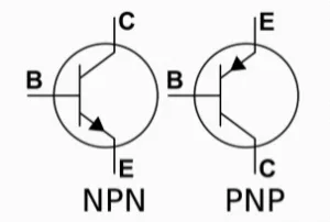
Terminology
BJT versus FET
- Bipolar junction transistor: Useful as amplifiers.
- Collector
- Emitter
- Base
- Field-effect transistor: Useful as motor drivers.
- Source, Drain, Gate
- MOSFET: metal-oxide-semiconductor FET
NPN (N-channel FET) versus PNP (P-channel FET)
- NPN versus PNP is how the semiconductors are layered.
- NPN: Not pointing in
- PNP: Pointing in permanently
Schematic symbols

Transformers
A transformer consists of two coils wound on a core. The core is made of layers of iron

The coils normally have many more turns than are shown in the drawing.
When a current is passed through the primary coil, it produces a magnetic field. The core is to provide a path for the lines of magnetic force so that they almost all pass through the secondary coil. Induction occurs only when there is a change in the magnetic field. So a transformer does not work with DC. When AC flows through the primary coil there is an alternating magnetic field. This induces an alternating current in the secondary coil.
Frequency: The frequency of the induced AC equals that of the inducing AC.
Amplitude: If Vv is the amplitude of the voltage in the primary coil, and Vs is the amplitude of the voltage in the secondary coil, then:
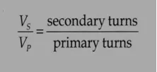
A transformer has 50 turns in the primary coil and 200 turns in the secondary coil. The amplitude of the primary AC is 9 V. What is the amplitude of the secondary AC?
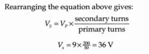
The amplitude of the secondary current is 36 V. These calculations assume that the transformer is 100% efficient.
- How to use electronic components
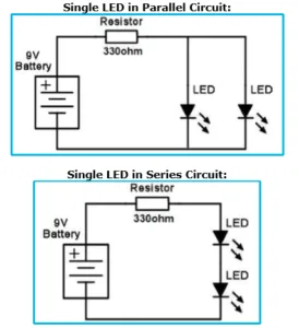
- Learn how to use resistor and LED
Set of materials:
o Battery clip connector
o 9V battery
o LEDs (different colors)
o Resistors (330Ω, 1KΩ, 2KΩ, 5KΩ, 10KΩ, 100KΩ)
o Simple solderless breadboard
2. Diode Rectifier Circuits
Rectifier is a circuit that converts AC to DC
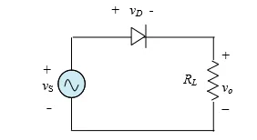
The following circuit shows half wave and full wave.
I. Half wave rectifier
Material used:
- AC voltage supply
- Diode
- Resistor (1K ohm)
- Breadboard
- Jumpers
II. Full wave rectifier
Material used:
- AC voltage supply
- Step-down transformer
- 4 diodes
- Load resistor
- Breadboard
- Jumpers

- Filter
The filter is a device that allows passing the dc component of the load and blocks the ac component of the rectifier output.
Thus the output of the filter circuit will be a steady dc voltage.
The filter circuit can be constructed by a combination of components like capacitors, resistors, and inductors.
The inductor is used for its property that it allows only dc components to pass and blocks ac signals. The capacitor is used so as to block the dc and allows ac to pass.
Half-wave Rectifier with Capacitor Filter
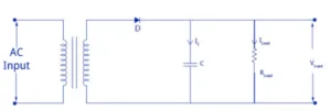
During the positive half cycle of the input ac voltage, the diode D will be forward biased and thus starts conducting. During this period, the capacitor ‘C’ starts charging to the maximum value of the supply voltage Vsm. When the capacitor is fully charged, it holds the charge until the input ac supply to the rectifier reaches the negative half cycle. As soon as the negative half supply is reached, the diode gets reverse biased and thus stops conducting. During the non-conducting period, the capacitor ‘C’ discharges all the stored charges through the output load resistance RLoad.
Thanks for reading this chapter 2

You may also like

Nyereka Tech and Tumba College Explore Opportunities for Collaboration

The Launch of our IoT Innovation Hub